SCADM3-H
Product Features
- Superior Grounding Performance: Independent ground contact linked to both shell and front panel delivers cleaner, more stable audio signals.
- Built to Last: Rated for over 1,000 mating cycles with a secure steel latch lock for dependable, long-term use.
- Premium Signal Quality: Gold-plated copper alloy contacts ensure low resistance and excellent corrosion resistance over time.
- Easy, Clean Installation: Rear-panel mounting keeps the front face tidy while simplifying assembly with standard self-tapping screws.
Contact us
Details
| Product Parameters | |
| Connection type | XLR |
| Gender | Male |
| Electrical Parameters | |
| Capacitance between contacts | ≤ 4 pF |
| Contact resistance | ≤ 6 mΩ |
| Dielectric strength | 1500V DC |
| Insulation resistance | > 10 GΩ (initial) |
| Rated current per contact | 6 A |
| Rated voltage | < 50 V |
| Mechanical Parameters | |
| Service Life | > 1000 mating cycles |
| Insertion force | ≤ 20 N |
| Withdrawal force | ≤ 20 N |
| Locking wiring | Latch lock |
| PCB Wiring | Horizontal PCB mount |
| Material and Environmental Parameters | |
| Housing | PA |
| Contacts | Cu alloy |
| Contact plating | Au |
| Flame-retardant grade | UL 94V-0 |
| Temperature range | -30°C ~ +80°C |
| Standards and Certifications | |
| Solderability | IEC 68-2-20 |
Downloads
Description
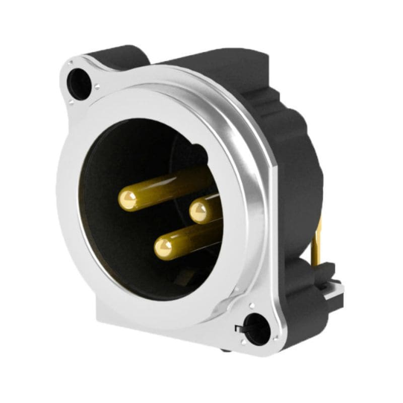
The SCADM3-H is a compact 3-pin XLR male panel-mount socket engineered for space-constrained audio and electronic equipment. Designed for horizontal PCB mounting and installed from the rear of the panel, this connector features a metal mounting flange with a steel latch lock for secure, reliable mating. Its independent grounding path—separated from the mating connector shell and front panel—ensures clean, stable signal transmission even in dense installation environments. With a compact 23 mm center-to-center spacing, the SCADM3-H is ideal for high-density connector layouts on mixers, amplifiers, stage boxes, and other professional audio equipment where board space is at a premium.
Key Features
- 3-Pin XLR Male Configuration: Standard XLR male socket for reliable balanced audio signal connections.
- Independent Grounding Design: Separate ground contact connects to both the mating connector shell and the front panel for improved noise immunity.
- Horizontal PCB Mount: Designed for horizontal circuit board installation, simplifying internal layout for compact enclosures.
- Secure Steel Latch Lock: Steel latch mechanism ensures a firm, dependable mating connection during use.
- Gold-Plated Contacts: Contact plating in gold improves conductivity and long-term corrosion resistance.
Electrical & Mechanical Specifications
- Contact Resistance: ≤ 6 mΩ, ensuring minimal signal loss across the connection.
- Capacitance Between Contacts: ≤ 4 pF, supporting signal integrity in sensitive audio circuits.
- Dielectric Strength: Rated at 1500V DC for robust insulation performance.
- Insulation Resistance: > 10 GΩ (initial), providing strong electrical isolation.
- Insertion/Withdrawal Force: ≤ 20 N for both, allowing smooth, comfortable mating and unmating.
- Service Life: Rated for over 1,000 mating cycles, supporting long-term reliable use.
Material and Environmental Specifications
- Contact Material: Copper alloy (Cu alloy) contacts for strong conductivity and durability.
- Contact Plating: Gold (Au) plating for enhanced corrosion resistance and stable long-term contact performance.
- Housing Material: PA (nylon) housing, offering good mechanical strength and dimensional stability.
- Flame Retardancy: UL 94 V0 rated housing material for enhanced fire safety compliance.
- Operating Temperature Range: -30°C to +80°C, suitable for a wide range of indoor and mobile equipment environments.
- Solderability: Compliant with IEC 68-2-20 standard for reliable PCB soldering performance.
Packaging and Accessories
- Standard Packaging: Supplied in blister box packaging, with 20 pieces per blister box.
- Carton Packaging: 120 pieces per inner carton, 5 inner cartons per master carton, totaling 600 pieces per master carton.
- Accessories: Shipped without additional accessories (no back fastener plate, screws, or nuts included).
Assembly Instructions
- Installation Method: Mount the socket on the rear side of the panel through the designated panel cut-out.
- Fastening Hardware: Secure using ST2.9 self-tapping screws, 8 mm in length.
- Torque Specification: Tighten screws clockwise to a torque of 0.45 Nm for a secure, damage-free fit.
- Panel Thickness Limit: Compatible with panels up to a maximum thickness of 3.0 mm.